One may wonder why proposing
a change in the identification of one of Titanic's ventilators
would merit a full article rather than just a simple post on the
message board. The reason is that evidence relating to the identity
of this ventilator has always been and continues to be minimal.
Much of the case for the change in the identification of this
ventilator is based on photo interpretation which requires sometimes
lengthy explanation of the logic involved in the identification
process. Some may also wonder why anyone would devote this much
effort to the identification of one ventilator. Beyond building
more accurate models, one of the objectives of this group is to
establish a permanent record of the actual appearance of Titanic.
That may sound like a simple task but it has taken a number of
people years to uncover what we know today. Much has been discovered
yet there are still areas which need to be researched. If you
will take the time to follow this discussion it may help if you
are studying an obscure area similar to this one. For the record,
when referring to ventilator #37 I will be referring to the ventilator
on the starboard/aft corner of the deckhouse under the 3rd funnel
of Titanic. The designation ventilator #37 is an arbitrary one
that was used in my Titanic Ventilator Inventory which is found
as part of the Titanic Modelling Tutorial.
History
One of the earliest efforts to rediscover the structure of Titanic
was the Entex 1/350 Titanic model project completed in the mid
1970's. As far as I know, Ken Marschall provided the technical
information for that project. At that time, available information
was quite limited. Not surprisingly, in this early attempt to
describe Titanic's structure, vent #37 was not even included on
the model. The next real development came sometime after the discovery
of Titanic in 1985. A Harland and Wolff photo of Olympic's ventilator
at this location was used as the model for Titanic's. Next, after
discussion with other members of this board, the configuration
was changed to the later and final configuration found on Olympic.
This improved ventilator is seen most clearly in Thomas Bonsall's
book "Titanic". The photo which shows this improved
ventilator is a photo of Olympic looking forward taken from the
top of the 4th funnel. The decision to
adopt this ventilator type as representative of Titanic's was
made in response to the Beken's forward 3/4 profile photo of Titanic.
It was noted that the rounding of the ouboard side of the ventilator
could not be the early Olympic type of ventilator found here.
It was logically assumed that during fitting out Titanic adopted
the type of ventilator found in the later Olympic photo in Bonsall.
The single piece of evidence that prompted the current proposed
change was a photo of the forward side of the final Olympic ventilator
found here. The photo is from "The Titanic Disaster as Reported
in the British Press April-July 1912" by Bryceson. Another
excercise which made the available evidence more clear was work
I have been doing in attempting to draw accurate scale d drawings
of the ventilators found on Titanic.
The Evidence
The evidence used to argue this case is somewhat sparse.
However, the evidence that does exist leads one to some firm conclusions.
The photos used are:
1. The Olympic 4th funnel photo found in Bonsall.
("Titanic" by Thomas Bonsall, p. 62)
2. The Bekens photo found in numerous references.
("The Discovery of the Titanic" by Robert
Ballard, p. 14-15), ("Titanic & Her Sisters
Olympic & Britannic" by Mckluskie, Sharpe and
Marriott, p.244-245)
3. The Odell photo of the forward 3rd funnel area.
("The Discovery of the Titanic" by Robert
Ballard, p.163)
4. The Harland and Wolff photo of the first
Olympic ventilator configuration in this
area. ("Anatomy of the Titanic" by Thomas
McKluskie, p.123, top)
5. The photo of the Olympic Marconi operators
forward of the Olympic's inverted 35 inch
Sirocco. ("The Titanic Disaster as Reported
in the British National Press, April-July 1912"
by Dave Bryceson, p.92)
Several drawings I have produced will be used to illustrate my
points:
1. Two drawings
from approximately the same angle as the Bekens
photo showing the difference that the available alternatives
for this would present. (A.jpg)
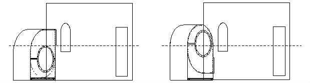
Figure A
2. A drawing comparing
the forward appearance of the two
ventilator alternatives. (B.jpg)
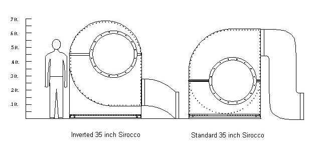
Figure B
3. A drawing showing an overhead view of the proposed
venitalator. (C.jpg)
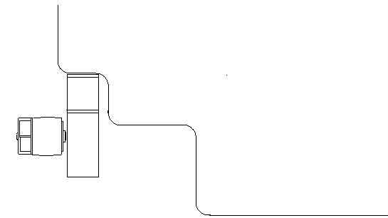
Figure C
Evidence was also taken from the detailed Olympic deck plan
found in "Anatomy of the Titanic" p.43 and "Titanic
& Her Sisters Olympic & Britannic" p. 102-103.
In addition, a video capture of a "lost" Titanic plan
was used (Video no longer comercially available).
Analysis
There is much that should probably preface the analysis but
I will try to proceed to the point as quickly as possible and
deal with side issues and alternatives later.
The photo that caused me to change my mind about Titanic's ventilator
is the photo of the Marconi operators standing in front of the
ventilator on Olympic that occupies the same position. I had
always wondered why the intake duct, which is about 35 inches
in diameter, didn't show up on the Bekens photo.
The Bekens photo exposes from half to three quarters of the
vent in a port to starboard direction. It can be
seen on the Marconi photo that the intake duct extends to at
least the middle of the duct. Also, as closely as I can estimate,
the height of the middle of the horizontal centerline of the
intake duct is in the 60 inch range. We know from the height
of the windows forward of this ventilator that anything above
at least 60 inches would be clearly seen also. What this means
is that given conservative estimates, we should at least be
able to see the starboard upper quarter of the intake duct IF
this was the same ventilator that was found on Olympic. If you
look at the Bekens photo you will see that this is not the case.
At this point I ruled out the Olympic style ventilator as a
candidate for this ventilator type. From plans we know this
was a 35 inch Sirocco fan at this location on both ships. The
only alternative left for Titanic was a standard 35 inch Sirocco
found in numerous places on the boat deck. After studying
numerous photos of this ventilator and
especially the O'dell photo to gauge dimensions I drew it on
my drafting program. I compared what this ventilator would look
like if it were in the same position and the facts have appeared
to fit. If the standard 35 inch Sirocco were placed in the same
position then its intake duct would be obscured completely by
the bulwark in the foreground of the Bekens photo. Both ventilators
would give roughly the same outboard profile in the Bekens photo
but the one fact that cannot be circumvented is that on the
Olympic's ventilator we would definitely see some of the intake
duct and we don't. We see no intake duct which would be entirely
consistent with the standard 35 inch Sirocco.
Questions
In order to more fully explain my position, I will pose and
answer some questions I had and which were posed to me in the
development of this position.
1. What was the difference between the standard
35 inch Sirocco ventilator and the one seen on Olympic
after 1912?
The Titanic's 35 inch Sirocco was just a standard sized ventilator
found in many places on the boat deck. This type of ventilator
either had no intake duct attachment or a large "curl"
type intake was attached to it. The Olympic had a one of a kind
arrangement for 35 inch ventilators in that it was simply an
inverted standard 35 inch Sirocco. I say "simply"
but there were several modifications. The upper rounded profile
was formed by the internal duct path of the standard 35 incher
with the outer fan housing removed. The output of the ventilator
was raised so that the entire ventilator stood about 10 inches
higher than the standard 35 incher which stood about 75 inches
tall. If you look at the O'Dell photo, you can see that there
is a flange which divides the standard 35 incher along the central
horizontal fan axis of the fan. For the standard 35 incher this
central horizontal fan axis is below the midline. Thiscentral
horizontal fan axis was about 30 inches from the deck. On the
inverted Sirocco this axis is raised to nearly 60 inches.
2. Why weren't either of the two types of 35
inch ventilators moved farther into the corner and thus closer
to the bulkhead?
The reason is that the intake duct needed to be unobstructed
because it was on this side that the fan could be removed or
replaced.
3. Why would there have been two diffent types
of ventilators?
There are ample precedents for ventilator differences between
Olympic and Titanic. This "why" question can't be
answered from available evidence. This doesn't preclude the
existence of different types of ventilators here though.
4. Since the Olympic's inverted 35 inch Sirocco
ducted into the bulkhead near the deck, what about Titanic's
ducting?
This part of the puzzle is still completely speculative. We
know from the early photo of Olympic's earliest ventilator that
they used an inverted 30 inch Sirocco so that it could duct
into the bulkhead near the deck. It appears from plans that
the same alterations were perfomed on Titanic to necessitate
the ducting into the bulkhead also at the deck level. Whatever
the ducting configuration, the duct from the ventilator on both
Titanic and Olympic had to span a distance of about 3 ft from
each ventilator's outboard position. Olympic had a simple angled
duct from it's low exit point on the ventilator down to the
base of the bulkhead.
5. What did Titanic's ducting look like?
Again we have to speculate. However, our guess can be educated.
If a simple angled duct were placed from the high exit point
(over 6 ft.) on the standard 35 incher on Titanic down to the
deck level of the bulkhead, the problem would be that because
of the steep angle and short span, the profile of the duct would
have been reduced about in half. This would have restricted
airflow. In order to keep the original duct dimensions, two
right angle elbows would have to have been employed to duct
from the this 6 ft. level down to the deck. This kind of elbow
and ducting was routinely used for the standard 35 inchers which
had "curl" intake attachments. For these ventilators
a right angle elbow turned the duct from horizontal to vertical
so that the duct could enter the deck. On this particular application,
there would have to have
been a second right angle elbow placed at deck level to direct
the duct horizontally into the bulkhead at the deck level. There
is ample room for this ducting arrangement and the ducting is
esentially "off the shelf".
6. Why didn't Titanic's standard 35 incher
just duct straight across horizontally into the bulkhead at
the higher level?
It could have. However, since the alterations on the other side
of this bulkhead were made very early on Olympic during fitting
out it can be assumed that they were also made on Titanic because
the plans show an identical configuration. So whatever the alterations
were that required a ducting position at deck level for Olympic,
we can reasonably assume that the same alterations also were
required for Titanic.
7. Since both Olympic's and Titanic's ventilators
were upgrades from Olympic's original inverted 30 incher, why
didn't they make an identical upgrade?
This is one of the tough "why" questions. There could
be many possible answers. For illustrative purposes I'll offer
one possible explanation. Early on it could have been discovered
that Olympic's inverted 30 inch Sirocco did not deliver the
required performance. To solve the problem they just took a
larger Sirocco (35 inch) and inverted it. Now that sounds simple
enough until you see the size of one of these things. The time
and expense of converting a standard 35 incher to an inverted
model may have been deemed excessive. To save money they may
have tried an experiment to see if just using a standard 35
incher and making an "S" shaped duct to enable it
to duct low would be effective. They probably knew that the
inverted model worked on Olympic and that they could still replace
Titanic's standard 35 incher with the inverted model if the
custom ducting didn't work as planned. Modifying only the
ducting would have been a much more cost effective alternative
if it worked. Since Titanic only had one voyage we will never
know what changes may have been made to her ventilators after
they were in service
for a period of time.
Those are some of the main questions I have dealt with.
In addition there a whole group of "what if" questions
that pose alternatives that while within the realm of possibility
are not within the realm of probability. Most of these questions
often disguise a desire to have a differnt answer fit the facts.
I follow Occam's Razor which states that the simplest answer
that fits the
facts is usually the right answer.
Conclusions
Vent #37 on Titanic should be understood as a standard 35 inch
Sirocco ventilator. The new evidence in the form of a close-up
photo of the previous postulated ventilator configuration eliminates
it as a possibility for the ventilator configuration in this
location.
The ducting is an educated guess based on the best available
evidence at the time of of this article. The precise ducting
may never be known. However, whenever it seems that there is
no possibility of any new evidence surfacing, that's when it
happens. Hopefully that new evidence will clarify the
remaining unknowns.
|